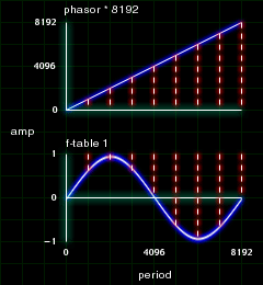
figure 4.1
| 401.orc |
|
|
|
|
|
|
|
| instr 1 |
|
|
|
| iamp |
= |
p4 |
|
| ifreq |
= |
p5 |
|
|
aphasor |
phasor |
ifreq |
|
atable |
table |
aphasor * 8192, 1,0 ,0, 1 |
|
out |
atable * iamp |
| endin |
|
|
|
| 401.sco |
|
|
|
|
|
|
|
|
|
| f1 |
0 |
8192 |
10 |
1 |
|
|
|
|
|
| i1 |
0 |
2 |
10000 |
262 |
This may seem like extra work to get the same effect as the OSCIL opcode. But now you know a little bit more about how OSCIL works under the hood. Not to mention, there are plenty more things you can do with this trick you can't do with the OSCIL. Keep reading.

Simulating a Sync Oscillator

The traditional analogue way of creating a sync oscillator has two main components, the master oscillator and the slave oscillator. The master oscillator defines the pitch of the singal by telling the slave to reset its cycle to the beginning. The frequency of the slave is independent of the master. When the master begins another cycle, the slave is forced to truncate its wavefrom and start at the beginning of its cycle. Thus, causing both the master and slave to have the same period length. The master is the control signal while the slave is the audio signal.
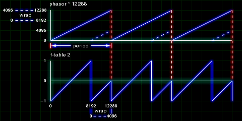
In Csound, we'll use the phasor technique to get near the same results. If we multiply our phasor by 12288 when our stored function table has a size of 8192, then the pointer will wrap itself around (providing the optional wrap argument in TABLE is on.) In other words, when the phasor is feeding values from 8193 to 12888 the TABLE pointer will actually be looking at 0 to 4096 in the stored function table.
In the figure below, the blue dotted lines point to the wrap around. The red dotted lines point to where the wave resets.

figure 4.2
| 402.orc |
|
|
|
|
|
|
|
| instr 1 |
|
|
|
| idur |
= |
p3 |
|
| iamp |
= |
p4 |
|
| ipch |
= |
cpspch(p5) |
|
| isync |
= |
p6 |
|
|
aenv1 |
linseg |
1, idur * .5, isync, idur * .5, 1 |
|
aphasor |
phasor |
ipch |
|
atable |
table3 |
aphasor * 8192 * aenv1, 1, 0,0, 1 |
|
out |
atable * iamp |
| endin |
|
|
|
| 402.sco |
|
|
|
|
|
|
|
|
|
|
|
|
|
| f1 |
0 |
8192 |
7 |
-1 |
8192 |
1 |
|
|
|
|
|
|
|
| i1 |
0 |
4 |
10000 |
6.00 |
8 |
|
| i1 |
4 |
4 |
10000 |
6.05 |
16 |
|
This creates a very dirty sounding sync. Aliasing is to blame.

Short Cuts to Creating Complex Rhythyms

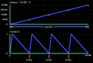
Here is a very easy use of the phasor to create complex rhythms in Csound. Instead of using the PHASOR for audio purposes, we can also use it to cycle through control signals. Create a stored function table using GEN 7 with a sharp attack and a long decay. Multiply the PHASOR by the size of the table (8192) and the number of times you want the rhythym to be triggered per beat. Multiply this TABLE with the amplitude of an OSCIL and you'll have yourself a very simple rhythmic instrumet. And its more user friendly in the score.

figure 4.3
| 403.orc |
|
|
|
|
|
|
|
| instr 1 |
|
|
|
| idur |
= |
p3 |
|
| iamp |
= |
p4 |
|
| ipch |
= |
cpspch(p5) |
|
| irate |
= |
p6 |
|
|
aphasor |
phasor |
irate |
|
atable |
table |
aphasor * 8191, 2 |
|
aosc1 |
oscil |
iamp, ipch, 1, -1 |
|
aosc1 |
= |
aosc1 * atable |
|
out |
aosc1 |
|
| endin |
|
|
|
| 403.sco |
|
|
|
|
|
|
|
|
|
|
|
|
|
|
|
|
|
|
|
|
|
|
|
|
|
|
|
|
|
|
|
|
|
|
|
|
|
|
|
|
|
| f1 |
0 |
8192 |
10 |
1 |
0 |
0 |
0 |
0 |
0 |
.5 |
0 |
0 |
.3 |
0 |
0 |
0 |
.2 |
0 |
0 |
.1 |
| f2 |
0 |
8192 |
-7 |
0 |
192 |
1 |
200 |
.6 |
7800 |
0 |
|
|
|
|
|
|
|
|
|
|
|
|
|
|
|
|
|
|
|
|
|
|
|
|
|
|
|
|
|
|
|
| i1 |
0 |
2 |
10000 |
7.00 |
4 |
|
|
|
|
|
|
|
|
|
|
|
|
|
|
|
| i1 |
+ |
. |
. |
7.05 |
3 |
|
|
|
|
|
|
|
|
|
|
|
|
|
|
|
| i1 |
+ |
. |
. |
7.02 |
8 |
|
|
|
|
|
|
|
|
|
|
|
|
|
|
|
| i1 |
+ |
. |
. |
7.07 |
6 |
|
|
|
|
|
|
|
|
|
|
|
|
|
|
|
| i1 |
+ |
. |
. |
7.00 |
.5 |
|
|
|
|
|
|
|
|
|
|
|
|
|
|
|
|
|
|
|
|
|
|
|
|
|
|
|
|
|
|
|
|
|
|
|
|
| i1 |
12 |
2 |
10000 |
7.07 |
4 |
|
|
|
|
|
|
|
|
|
|
|
|
|
|
|
| i1 |
+ |
. |
. |
. |
4 |
|
|
|
|
|
|
|
|
|
|
|
|
|
|
|
| i1 |
+ |
. |
. |
. |
4 |
|
|
|
|
|
|
|
|
|
|
|
|
|
|
|
| i1 |
+ |
. |
. |
. |
4 |
|
|
|
|
|
|
|
|
|
|
|
|
|
|
|
| i1 |
+ |
. |
. |
. |
3 |
|
|
|
|
|
|
|
|
|
|
|
|
|
|
|
| i1 |
+ |
. |
. |
. |
2 |
|
|
|
|
|
|
|
|
|
|
|
|
|
|
|
| i1 |
+ |
. |
. |
. |
2 |
|
|
|
|
|
|
|
|
|
|
|
|
|
|
|
| i1 |
+ |
. |
. |
. |
8 |
|
|
|
|
|
|
|
|
|
|
|
|
|
|
|
| i1 |
+ |
. |
. |
. |
3 |
|
|
|
|
|
|
|
|
|
|
|
|
|
|
|
| i1 |
+ |
. |
. |
. |
12 |
|
|
|
|
|
|
|
|
|
|
|
|
|
|
|
|
|
|
|
|
|
|
|
|
|
|
|
|
|
|
|
|
|
|
|
|
| i1 |
+ |
2 |
10000 |
7.072 |
2 |
|
|
|
|
|
|
|
|
|
|
|
|
|
|
|
| i1 |
+ |
. |
. |
. |
3 |
|
|
|
|
|
|
|
|
|
|
|
|
|
|
|
| i1 |
+ |
. |
. |
. |
8 |
|
|
|
|
|
|
|
|
|
|
|
|
|
|
|
| i1 |
+ |
. |
. |
. |
6 |
|
|
|
|
|
|
|
|
|
|
|
|
|
|
|
| i1 |
+ |
. |
. |
. |
6 |
|
|
|
|
|
|
|
|
|
|
|
|
|
|
|
| i1 |
+ |
. |
. |
. |
3 |
|
|
|
|
|
|
|
|
|
|
|
|
|
|
|
| i1 |
+ |
. |
. |
. |
6 |
|
|
|
|
|
|
|
|
|
|
|
|
|
|
|
| i1 |
+ |
. |
. |
. |
3 |
|
|
|
|
|
|
|
|
|
|
|
|
|
|
|
| i1 |
+ |
. |
. |
. |
12 |
|
|
|
|
|
|
|
|
|
|
|
|
|
|
|
| i1 |
+ |
. |
. |
. |
4 |
|
|
|
|
|
|
|
|
|
|
|
|
|
|
|
| e |
|
|
|
|
|
|
|
|
|
|
|
|
|
|
|
|
|
|
|
|

Building a Phasor with OSCIL

Building a Phasor is quite easy. Create an f-table with GEN 7 that rises from 0 to 1.
f2 0 8192 7 0 8192 1
Then use an OSCIL to cycle through this stored function table.
aphasor oscil 1, 440, 2
This is now identical to the PHASOR opcode.

Building a Non-linear Phasor

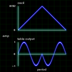
The only difference in creating this versus the last example is that we'll make a different shape in our f-table. If the f-table stores a triangle waveform and applied to a TABLE, the TABLE will read to the end and back to the beginning of a stored wave during one period. Figure 4.4 shows visually what happen when you do this.

figure 4.4
| 404.orc |
|
|
|
|
|
|
|
| instr 1 |
|
|
|
| idur |
= |
p3 |
|
| iamp |
= |
p4 |
|
| ipch |
= |
cpspch(p5) |
|
| ishape |
= |
p6 |
|
|
aclock |
oscil |
.5, ipch, ishape, -1 |
|
aclock |
= |
aclock + .5 |
|
atable |
table |
aclock * 8191, 1, 0,0, 1 |
|
out |
atable * iamp |
| endin |
|
|
|
| 404.sco |
|
|
|
|
|
|
|
|
|
|
|
|
|
|
|
|
|
| f1 |
0 |
8192 |
10 |
1 |
|
|
|
|
| f2 |
0 |
8192 |
-7 |
-1 |
4096 |
1 |
4096 |
-1 |
|
|
|
|
|
|
|
|
|
| i1 |
0 |
2 |
10000 |
7.00 |
2 |
|
|
|


