pdhalfy
pdhalfy — Distorts a phasor for reading two unequal portions of a table in equal periods.
Description
The pdhalfy opcode is a variation on the phase distortion synthesis method of the pdhalf opcode. It is useful for distorting a phasor in order to read two unequal portions of a table in the same number of samples.
Initialization
ibipolar -- an optional parameter specifying either unipolar (0) or bipolar (1) mode. Defaults to unipolar mode.
ifullscale -- an optional parameter specifying the range of input and output values. The maximum will be ifullscale. The minimum depends on the mode of operation: zero for unipolar or -ifullscale for bipolar. Defaults to 1.0 -- you should set this parameter to the maximum expected input value.
Performance
ain -- the input signal to be distorted.
aout -- the output signal.
kShapeAmount -- the amount of distortion applied to the input. Must be between negative one and one (-1 to 1). An amount of zero means no distortion.
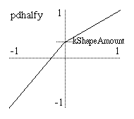
Transfer function created by pdhalfy and a negative kShapeAmount.
The pdhalfy opcode calculates a transfer function that is composed of two linear segments (see the graph). These segments meet at a "pivot point" which always lies on the same vertical axis. (In unipolar mode, the axis is x = 0.5, and for bipolar mode it is the y axis). So, pdhalfy is a variation of the pdhalf opcode that places the pivot point of the phase distortion pattern on a vertical axis instead of a horizontal axis.
The kShapeAmount parameter specifies where on the vertical axis this point falls. When kShapeAmount is zero, the pivot point is in the middle of the output range, forming a straight line for the transfer function and thus causing no change in the input signal. As kShapeAmount changes from zero (0) to negative one (-1), the pivot point downward towards the bottom of the graph. As it changes from zero (0) to positive one (1), the pivot point moves upward, producing an inverted pattern.
If the input to pdhalfy is a phasor and the output is used to index a table, the use of pdhalfy will divide the table into two segments of different sizes with each segment being mapped to half of the oscillator period. Values for kShapeAmount that are less than zero will cause less than half of the table to be read in the first half of the period of oscillation. The rest of the table will be read in the second half of the period. The reverse is true for values of kShapeAmount greater than zero. Note that the frequency of the phasor is always unchanged. Thus, this method of phase distortion can only produce higher partials in a harmonic series. It cannot produce inharmonic sidebands in the way that frequency modulation does. pdhalfy tends to have a milder quality to its distortion than pdhalf.
pdhalfy can work in either unipolar or bipolar modes. Unipolar mode is appropriate for signals like phasors that range between zero and some maximum value (selectable with ifullscale). Bipolar mode is appropriate for signals that range above and below zero by roughly equal amounts such as most audio signals. Applying pdhalfy directly to an audio signal in this way results in a crude but adjustable sort of waveshaping/distortion.
A typical example of the use of pdhalfy is
    aphase    phasor     ifreq
    apd       pdhalfy    aphase, kamount
    aout      tablei     apd, 1, 1
Examples
Here is an example of the pdhalfy opcode. It uses the file pdhalfy.csd.
Example 617. Example of the pdhalfy opcode.
See the sections Real-time Audio and Command Line Flags for more information on using command line flags.
<CsoundSynthesizer>
<CsOptions>
; Select audio/midi flags here according to platform
-odac     ;;;realtime audio out
;-iadc    ;;;uncomment -iadc if realtime audio input is needed too
; For Non-realtime ouput leave only the line below:
; -o pdhalfy.wav -W ;;; for file output any platform
</CsOptions>
<CsInstruments>

sr = 44100
ksmps = 32
nchnls = 2
0dbfs  = 1

instr 5

    idur        = p3
    iamp        = p4
    ifreq       = p5
    iamtinit    = p6      ; initial amount of phase distortion
    iatt        = p7      ; attack time
    isuslvl     = p8      ; sustain amplitude
    idistdec    = p9      ; time for distortion amount to reach zero
    itable      = p10

    idec        =  idistdec - iatt
    irel        =  .05
    isus        =  idur - (idistdec + irel)

    aenv        linseg      0, iatt, 1.0, idec, isuslvl, isus, isuslvl, irel, 0, 0, 0
    kamount     linseg      -iamtinit, idistdec, 0.0, idur-idistdec, 0.0
    aosc        phasor      ifreq
    apd         pdhalfy     aosc, kamount
    aout        tablei      apd, itable, 1

                outs        aenv*aout*iamp, aenv*aout*iamp
endin

</CsInstruments>
<CsScore>
f1 0 16385 10 1                 ; sine
f3 0 16385  9 1 1 270           ; inverted cosine

; descending "just blues" scale

; pdhalfy with cosine table
t 0 100
i5 0 .333 .6    512     1.0   .02  0.5  .12   3
i. + .    .     448     <
i. + .    .     384     <
i. + .    .     358.4   <
i. + .    .     341.33  <
i. + .    .     298.67  <
i. + 2    .     256     0.5
s

; pdhalfy with sine table
t 0 100
i5 0 .333 .6    512     1.0   .001 0.1  .07   1
i. + .    .     448     <
i. + .    .     384     <
i. + .    .     358.4   <
i. + .    .     341.33  <
i. + .    .     298.67  <
i. + 2    .     256     0.5
e
</CsScore>
</CsoundSynthesizer>
See Also
More information about phase distortion on Wikipedia: http://en.wikipedia.org/wiki/Phase_distortion_synthesis